If you do an online search, you’ll find that the only solution to get a speed reading from an RC car is by using an external GPS device attached to the car. But what if we could have a cool speedometer reading right on our view, just like that we saw on F1 TV?
So we took the effort to put this idea into practice by performing a “technology transfer” from the drone arena to the RC world. We used the devices commonly available on quadcopters and fitted them to an RC car – notably a flight controller and a GPS module to calculate the speed. We then display the speed readings on a pair of FPV goggles.
List of Required Items
Below is the list of items with the exact parts we are using in this tutorial.
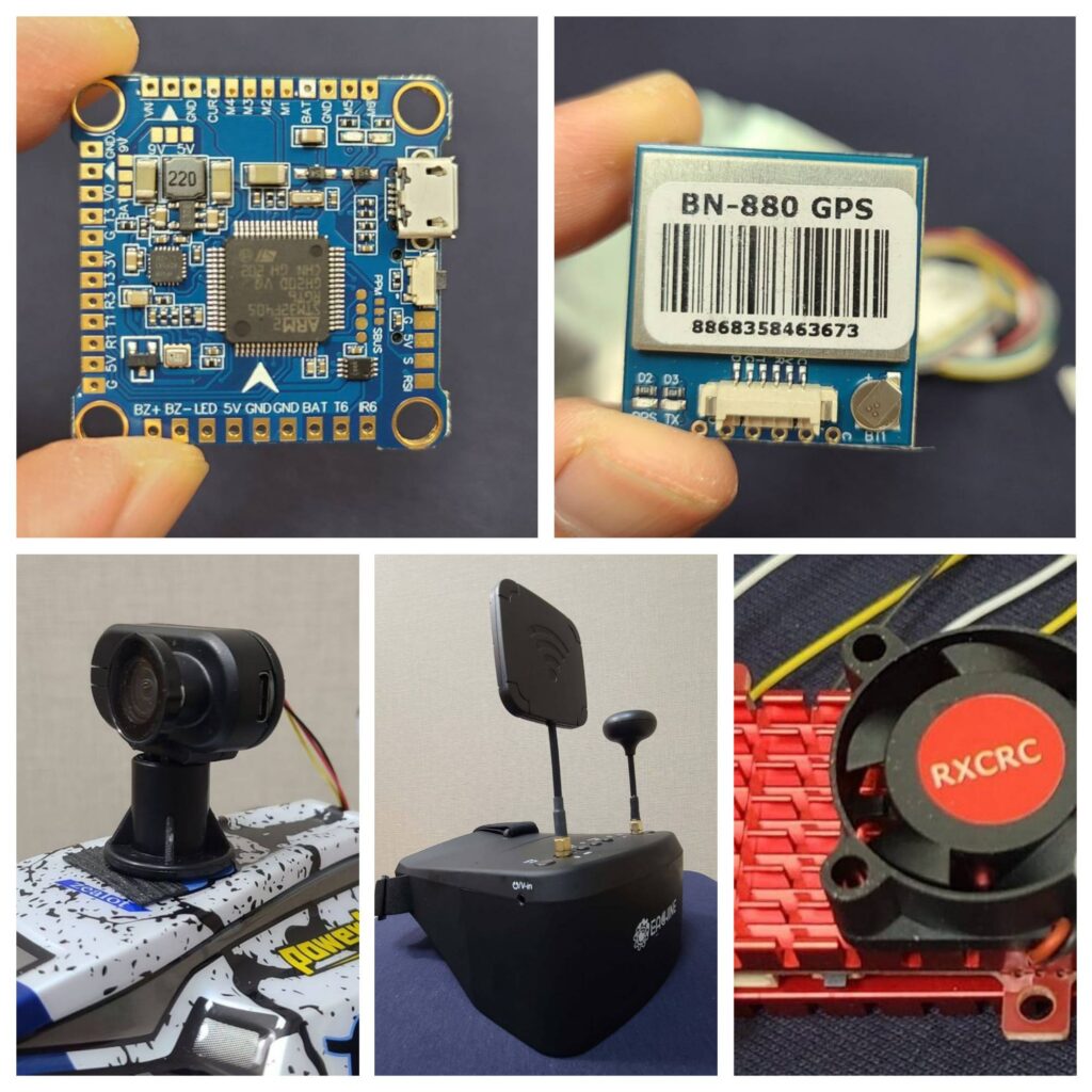
- A flight controller – we shall use the popular and affordable F4 flight controller.
- A GPS module – we recommend the BN-880 unit which could lock on GPS satellites rather quickly.
- Betaflight Configurator – a free software to configure the speedometer on our onboard display.
- An FPV camera – we shall use the Hawkeye Thumb 4K camera.
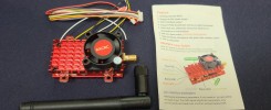
- A video transmitter – let’s use the EWRF 2W video transmitter.
- A flight controller protective case – a makeshift case made out of an SD card case.
What is a Flight Controller and Its Purpose
As its name implies, a flight controller is a device that controls the functions of sensors and other parts of a drone or an RC aircraft. It acts like the brain for the entire airborne vehicle. One of its useful functions is to communicate with a GPS module to perform navigational operations such as location indication, flight planning, autonomous navigation, return to home, as well as providing speed reading. As you can understand, we are borrowing this flight controller technology for our RC ground vehicle.
We won’t be using all those functions except speed reading. The GPS and flight controller determine speed by analyzing changes in position over time.
There are many other useful telemetries such as pitch and roll which we will discuss in our next tutorials. For now, we only want a speedometer.
In this tutorial, we shall use the popular F4 flight controller embedded with the STM32F4 series microcontroller – STM32F405 is the exact microcontroller we are using. It is already installed with the BetaFlight firmware.
There are multiple manufacturers for these F4 controllers so don’t be confused with the name of the brands as all of them carry the same microcontroller variant.
How to Wire Everything Together
Below is a wiring diagram of the F4 flight controller. It is the heart of what we are doing because everything else goes through it. You need to perform soldering work to get the wiring work done.
The first thing to do is to wire the power input. Here, we shall take the power cables from the balance leads of a LiPo battery and wire them to the BAT pad and GROUND pad shown below at the top left corner.
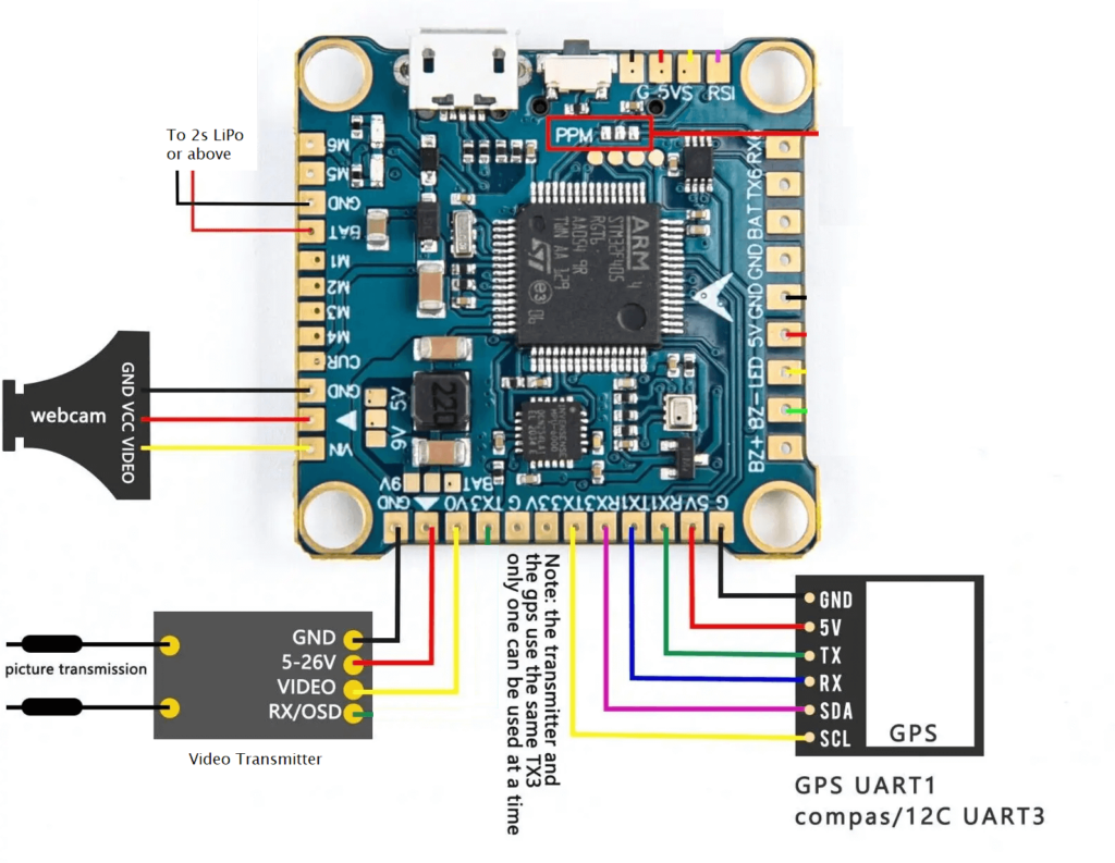
To wire the FPV camera (shown as a webcam in the diagram), we can tap the 5-volt output from the flight controller and connect it to the camera. However, since we are using the Hawkeye Thumb 4K camera that only accepts 5.5V and above, we have to tap the power from our LiPo battery. The yellow wire represents the video output from the camera. We should wire the video out to the VIN pad of the flight controller which is the video input.
Then, the video signal shall go out from the flight controller to the video input of the video transmitter. The flight controller actually takes the video feed from the camera and adds the speedometer display to the video feed and sends the processed video signal to the video transmitter.
We could tap the power source from the flight controller’s 5-volt output but we shall not perform that in this tutorial because the transmitter accepts a minimum voltage of 6 volts. Thus, we shall draw the power from our LiPo. Some video transmitters include an OSD port but we shall not cover this in this tutorial.
To wire the GPS module, we shall use the 5-volt output from the controller to power the GPS unit. At the TX port, meaning the transmit port, we shall wire it to RX1, not TX1. Remember, this GPS module shall connect to the UART 1 port of the flight controller, represented by the number “1” on the pad labels, such as TX1 and RX1. For the TX1 pad, we need to connect it to the RX port on the GPS module. We shall ignore the SDA and SCL ports which are meant for compass use.
You may need to buy separate JST connectors to connect the different parts together. This depends on your LiPo battery leads and the parts you use.
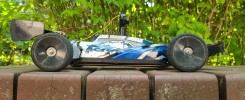
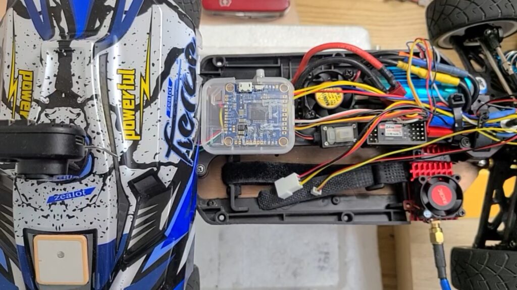
Below is what the wired parts look like on our RC car. The flight controller is enclosed in a DIY plastic case.
What is Betaflight Configurator
The Betaflight Configurator is an open-source software used to configure and tune Betaflight firmware running on flight controllers in drones and other multirotor aircraft. It provides a user-friendly interface to customize various flight parameters and monitor sensor data. But in our RC car context, we will not use most of the available features and only focus on speed telemetry for now. We shall explore other telemetries such as pitch and roll readings to balance on our RC car in another tutorial.
Betaflight is the recommended firmware over iNav or ArduiPilot because of its ease of use, popularity, good hardware support and it was primarily designed for racing.
Our F4 flight controller has already been installed with BetaFlight firmware so we need to configure it by downloading the free BetaFlight Configurator. Once we have downloaded and installed this software, we shall have something as shown below.
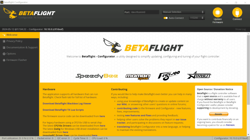
Next, we need to use a USB data cable to connect the flight controller to our PC. The BetaFlight Configurator should be able to detect our flight controller in one of the communication ports. If so, hit Connect.
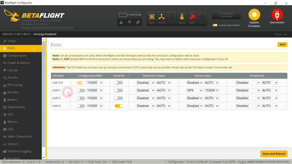
Once connected, the first thing to do is go to the ports menu to set up the communication port for the GPS module. So, go to UART1 and set the sensor input to GPS. Then, set the communication speed. You may set it to Auto or any value that works. This may require some trial and error. Once done, click on the “Save and Reboot” button.
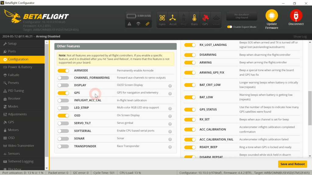
Next, go to the Configurations tab and enable GPS and OSD. Remember to save and reboot.
Then, go to the GPS menu and select the protocol. Usually, the protocol is UBLOX. And enable “Auto Config” and “Use Galileo” options. Then, hit the “Save and Reboot” button.
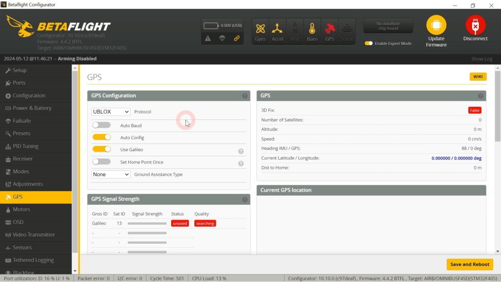
Once your GPS is working, we should be able to see the yellow GPS icon on top. If the GPS icon is red, it means the GPS module is working but is not able to lock into any satellites. Ensure your RC car is someplace outdoor or near the window in order to get the satellite signals.
It usually takes under a minute to lock on to sufficient GPS satellites. Sometimes more time is needed.
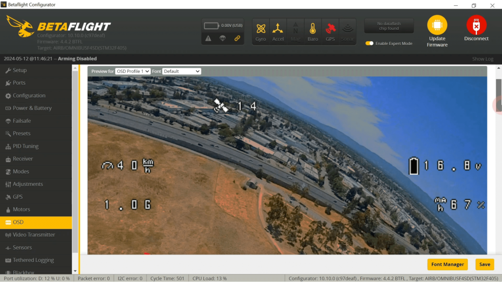
Next, go to the OSD menu. OSD stands for On Screen Display. This is where we shall configure our speedometer display. We shall use OSD Profile 1 and the default font.
First, we should display how many GPS satellites we have locked into because we use GPS to measure our speed. Thus, we should enable the “GPS sats” options. For the speedometer, we enable the “GPS speed” option.
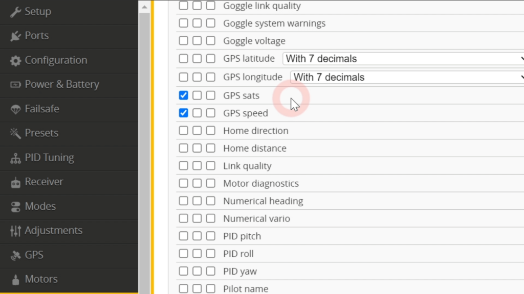
We can also activate the G-force reading and battery voltage and battery usage telemetries. There’s also a warning display, to display warning messages like low battery.
We can set the speed reading to miles per hour (mph) by selecting the imperial units or kilometers per hour (kph) by choosing metric units.
One of the intuitive capabilities of Betaflight is its drag-and-drop functionality when displaying OSD data. We can adjust the display positions by dragging and dropping. To move a display, click on the display and drag it to a new position. Once done, hit the save button.
Displaying the Speedometer
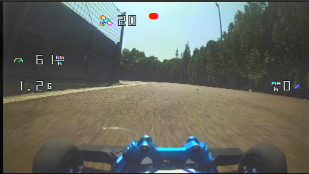
Finally, to view the speed readings, we just have to put on our FPV headsets and perform an auto search to find the video transmitter’s broadcasted video signal. Once we have tuned in, below is what we shall get on our headset display – a speedometer reading with other telemetries.
Speedometer is Just the Tip of the Iceberg
There is more RC car related data that we can add such as roll, pitch and yaw readings to measure the car’s stability. Distance traveled and throttle position are some other handy telemetries we can obtain. The speed’s the limit, so have fun!
This tutorial contains affiliate links to help us pay our bills.